imenada Imen Datis Asia Co

What is piping? Familiarity with industrial plumbing

What is piping?

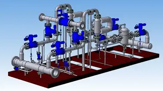
Industrial piping refers to a system consisting of pipes, fittings, and other related components used to transport or transport fluids (such as water, gas, oil, steam, chemicals, and the like). These systems are used in industrial and civil projects, including power plants, chemical, petrochemical, oil and gas, refineries, and other industries, as well as firefighting equipment.

Piping requires precision in terms of design, materials, and technical components. These systems should be designed and implemented according to the type of fluid, pressure, temperature, and chemical properties of the materials used. Failure to follow piping principles can lead to problems such as leaks, breaks, or problems in system performance.

Piping or industrial piping is a system consisting of several pipes and various connections that are used to transfer or refine fluids in industrial and construction projects. This part of projects is known as one of the most important and sensitive components. The components used in piping systems such as pipes, fittings, valves, supports and pipe racks, their types, design principles, required documents, principles of stress analysis, basics of support and materials science are covered in this training.

Main titles

What are the types of piping systems?

Piping systems are used in most industries. These systems are divided into different categories based on different applications, including power plant piping, process piping, transmission piping, refrigeration, building installations, service piping, slurry transfer, etc. The term “piping” is used primarily to refer to process piping, but all types of piping systems for conveying fluids for various applications include piping.  

In addition to process or plant piping,  other piping systems include:

Plumping: This system is used for potable water transfer, ventilation, heating/cooling, sewage discharge, drainage, gas transfer, etc. inside the building.
Civil Piping: Municipal services including water, gas and sewage are provided to residential, commercial, industrial and public buildings through this type of piping.
Service Piping: This type of piping provides the connection of building systems to municipal services.
Transportation Piping: It is a long piping that is used to transfer fluids in short and long distances.
Refrigeration Piping: This system reduces the ambient temperature by using a combination of refrigerant and oil.
Marine Piping: This system is used to transfer fluids in water or underwater structures.

What is power plant piping?

Power piping, or “power piping”, as a system, is mainly used in power generation plants, industrial plants, geothermal systems, and large-scale central heating/cooling systems. Power piping basically benefits from the energy obtained from the circulation of steam and water to perform various operations. As defined by the ASME standard, non-service piping systems are known as plant piping.

What are the types of valves in piping?

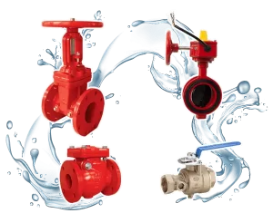
Industrial valves used in piping systems have many different types and are divided into the following types based on their structure and function:

Gate Valve:
A gate valve uses a barrier to turn off and on the flow. By changing the state of the barrier, the flow is completely opened or closed.

Globe Valve:
The flow control mechanism in this spherical valve consists of a disk in the shape of an incomplete cone or hemisphere. This type of valve is used to gradually decrease or increase the flow.

Angle Valve:
It is used to gradually increase or decrease the flow and change its direction.

Check Valve:
Check valves prevent fluid from returning and moving in the opposite direction. Oscillating one-way valves and pressure one-way valves are of this category.

Ball Valve:
It uses a hollow metal ball as a regulator and completely blocks or opens the flow path.

plug valve:
It is a type of valve with a cylindrical or hollow cone regulator, which can adjust the flow or completely block it by rotating in the direction of its axis.

Butterfly Valve:
A butterfly valve is used to isolate or regulate fluid flow and consists of a rotating circular disc.

Drain valve or relief valve :
It is used to maintain the system pressure at a safe level and opens when the pressure increases too much and closes when the pressure returns to a safe level.

Control Valve:
Usually, automatic ball valves are used as control valves to monitor and adjust system changes.

Diaphragm Valve:In a diaphragm valve, the fluid flow path is controlled by an elastomeric diaphragm.

Pinch Valve:
It consists of an elastic hose or tube with a part connected to the elastic part, and applying pressure to the flexible part results in the contraction of the elastic part and the closing of the fluid movement path.

Another criteria for dividing industrial valves is their mechanical movement. Based on this, the types of valves are:

Valve with linear movement:
In linear valves, the stem or duct member moves in a straight line to pass, stop or adjust the fluid flow. Types such as sliding, spherical, diaphragm, throat and one-way pressure valves are of this category.

Rotary valve:
In rotary valves, the stem or valve member performs its function by moving in a circular or angular path. Butterfly, ball, samouri and one-way oscillating valves are types of rotary valves.

Quarter turn valve:
Some rotary valves provide the possibility of fully opening or closing the duct with a quarter movement (0 to 90° angle).

What is Velo class?

The class of industrial valves is defined as a criterion for evaluating the performance of these devices under operating pressure and temperature conditions. The valve class, like the flange class, is represented using numerical coding. The ASME B16.34 standard is one of the most widely used standards for the design of industrial valves. Based on this standard, valves are divided into different classes including 150, 300, 400, 600, 900, 1500, 2500 and 4500. As an example, the table below shows the specifications of class 150 and 300 carbon steel valves (according to ASTM A216 standard). These specifications for higher grades and other materials are given in full in ASME B16.34.

Who is a piping expert or piping engineer?

A piping engineer is a person who is responsible for designing and implementing piping systems for transporting water, gas, oil, sewage and other similar materials. This professional is mainly involved in all phases related to the design and implementation of plumbing, including the creation of preliminary drawings, the selection of suitable materials for the manufacture of the necessary equipment, and the supervision of the quality of the system implementation process. Graduates of mechanical, chemical, civil, and facilities engineering are among the people who can continue their engineering career in the field of piping.

What are piping equipment or components?

Piping items are a set of parts needed to run piping systems. The main items of piping systems include pipes, supports, pipe racks, fittings, flanges, and valves.

The main piping components are:

1. Pipe: the way to transport fluids. They are usually made of steel, iron, PVC or other materials.

2. Fittings: to connect pipes to each other or to other components such as valves or supports.

3. Valve: to control fluid flow and adjust pressure.

4. Support: To support and maintain the pipes as part of the structure.

5. Pipe Rack: A structure that supports pipes and piping equipment at different heights.

What is a pipe?

The pipe is known as one of the main equipment used in fluid transmission systems. Different fluids are usually transferred to the desired location through pipes with a circular cross-section. The dimensions and mechanical characteristics of the pipe are among the basic parameters for choosing this equipment in piping systems. In process factories, pipes made of steel, cast iron, brass and copper are generally used. To display pipe dimensions, the following abbreviations are used:

NPS: Nominal Pipe Size
DN: nominal pipe diameter
ID: Inner diameter of pipe
OD: Tube outer diameter
SCH: Scajol number or pipe wall thickness
STD: Standard wall thickness or standard weight pipe
XS: heavy tube
XXS: Extra heavy tube

Showing the dimensions of pipes is usually done with the two criteria of diameter and thickness. Piping systems are divided into two categories, “Small Bore” and “Large Bore” based on these dimensions. In general, pipes with a nominal diameter less than or equal to 50 mm are used in the small section system and pipes with a nominal diameter greater than 50 mm are used in the large section system. One of the other criteria for dividing pipes in piping systems is the shape of their ends. Accordingly, the pipes are classified as smooth, beveled and threaded. Some commonly used pipes and abbreviations used to represent them in the piping system include:

BBE: double beveled ends
TBE: two threaded ends
PBE: Two smooth ends
BLE/TSE: Chamfered large end and threaded small end

What is the difference between pipe and tube?

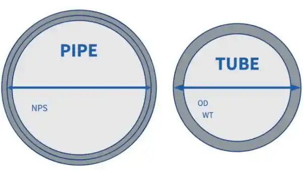
The tube is one of the widely used equipments for transferring fluids. Due to their similarities, the terms pipe and tube are often used interchangeably. However, a precise definition of the two can reveal their fundamental differences:

Pipe: A circular hollow sculpture that is used to transport liquids, gases and other materials, and its dimensions are displayed nominally.
Tube: A hollow sculpture with circular, rectangular, square or oval shapes whose external diameter and wall thickness are specified.

What is Pipe Support?

Pipe support or “support” is an element that transfers the loads applied by the pipe to the supporting structures. The weight of the pipe, fitting, passing fluid and covers are covered by the loads applied to the pipe support. Containment, guidance, impact absorption and maintenance of special loads are among the main functions of pipe support. In very high or low temperature conditions, insulating materials are used in the construction of this element. The pipe support configuration depends on the loading and operating conditions of the piping system. Based on these needs, the pipe support is divided into different types, including rigid, spring and shock absorbing.

What is Pipe Rack?

A “pipe rack,” or “pipeline,” serves as the main artery of a process unit and is used to hold supports, power cables, instrumentation, and other related components. In some cases, the pipe rack is also used as a place to store mechanical equipment such as tanks and valve access platforms. Pipes connected to the main pipe rack usually transport material between equipment or warehouses. It should be noted that pipe racks are not considered pipe racks even with the storage of pipe parts. Various types of pipes are used in the pipe rack, including service pipes used to convey steam, cooling water, fire water, fuel, etc. These pipes are mainly installed in the middle of one-story pipe racks or the top floor of two-story pipe racks. Placement of process pipes is also done outside the location of service pipes or the lower floor. Also, safety pipes are always installed outside the pipe rack.

What is a fitting or piping connections?

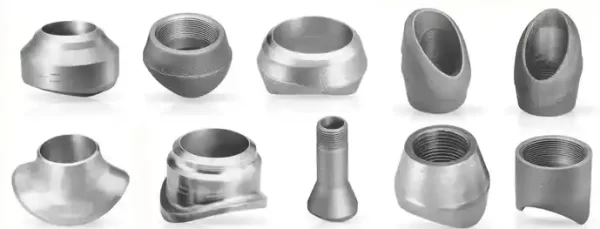
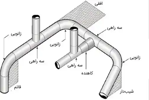
Fittings or, more precisely, “fittings” are components that are used to connect pipes to each other and cover pipe openings. The use of fittings makes it possible to change the path of the pipes, create branches and change the dimensions of the pipes. Fittings for pipes with a nominal diameter (NPS) greater than 75 mm are usually made by butt welding, while for pipes with an NPS less than 75 mm, socket welds (high pressure connections) or bolts are used. will be Some common types of piping fittings include elbows, tees, tees, pipe-to-pipe branches, reducers, caps, plugs, nipple switches, and weld sockets.

What is a knee and what is its use?

Elbow is one of the most widely used and basic fittings used to change the direction of pipes. These connections usually exist in two types of 45 and 90 degrees in the piping system. Based on the turning radius, the elbows are divided into two categories: LR (long radius) and SR (short radius). In welded fittings, the distance from the center to the end of the LR elbow is equal to 1.5 nominal pipe size (NPS) and for the SR elbow is equal to the nominal pipe size.

If the knee class is not specified, the LR type is considered as default. There are many types of elbows, and one of the most widely used is the miter elbow. This type of elbow is formed by chamfering the ends of several pipes and connecting them together. The miter elbow is mainly used in ventilation and air conditioning duct piping systems.

What is a tee and what is its use?

A T-shaped connection or tee is a type of connection that is used to create a branch in the path of pipes and piping system. This connection is usually divided into two types: direct and reducing tees. In this system, the main pipe from which the branch is taken is known as “Header” and the pipes connected to the tee are known as secondary pipes.

What is a reducer and what is its use?

A reducer is a tool used to connect pipes of different dimensions in a piping system. This tool is divided into two categories: concentric and non-concentric. In the concentric reducer, the central axis of the tubes is in the same direction. But in the non-concentric reducer, there is a distance or offset between the central axis of the pipes, which is equal to half the difference between the diameters of the two pipes.

The smooth surface of the non-concentric reducers can be run either downward (FOB configuration) or upward (FOT configuration). If running a FOB configuration, the reducer can be held by a pipe rack.

What is pipe-to-pipe branching and what is its use?

Stub-In connection or pipe-to-pipe branching is one of the most common methods to create branching in piping systems. This method is done by drilling a hole in the body of the main pipe and then the secondary pipes are welded to this hole. Next, several reinforcement pads are used to increase the strength around the joint area and cavity. The image below depicts an example of Stub-In implementation with allowed intervals.

What is a cap and what is its use?

A cap is a tool used to block open ends of pipes. The basic purpose of this device is to protect the ends of pipes with various shapes and prevent fluid leakage in the piping system. Caps are available in various shapes (circular, round, rectangular, U-shaped, I-shaped, hexagonal), construction materials (aluminum, polyethylene, stainless steel) and dimensions.

What are screw and silent weld fittings?

Screw fitting and “Socket Weld” method are two common methods for connecting pipes with a nominal diameter less than or equal to 75 mm (3 inches). In the silent weld method, the fitting piece penetrates into the pipe and then the area between the pipe and the fitting is welded.

What is a nipple and what is its use?

Nipple or “Swage Nipple” is a type of reducer that is used to connect pipes to screw and socket weld fittings in piping systems.

What is the cap and what is its use?

A cap or “plug” is a device with the same function as a cap, except that caps cover the end of the pipe, while plugs prevent fluids from escaping by sinking into the end of the pipe.

What is a flange in piping?

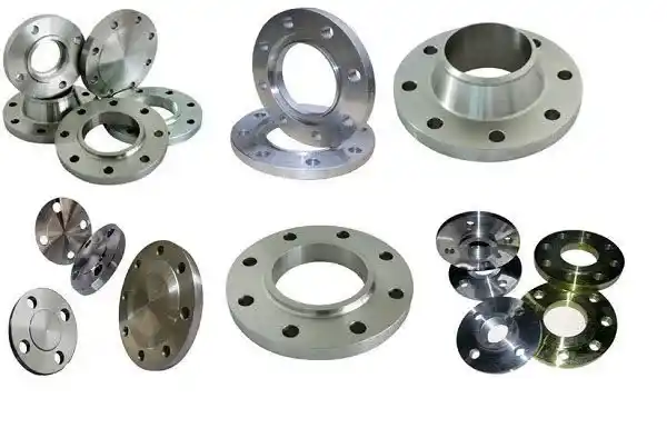
A flange is a circular piece with several holes used to connect pipes, nozzles, valves, pumps and other equipment in piping systems. These flanges provide easy access for cleaning, inspection and repair of piping systems. Easy opening for repair, maintenance and inspection makes this equipment a convenient and efficient alternative to welded and bolted connections. The tools used to connect flanges include screws, nuts and gaskets. The gasket is used to seal and ensure no leakage of fluids between two levels of connecting equipment.

What is flange class?

Flange class is a coding system used to identify flange types based on physical characteristics. This flange class is also known as a pressure rating, and this rating displays the maximum allowable pressure at a certain temperature. Steel flanges are available in different grades such as 150, 300, 400, 600, 900, 1500 and 2500. For example, a Class 150 flange can be used in piping systems with a maximum pressure of 150 pounds per square inch (psi) or 10.3 bar and a temperature of 500°F or 260°C.

As the temperature in the system increases, it is recommended to use a flange with a higher class. For example, in a system with an operating temperature of 750°F (399°C), the maximum allowable pressure is 100 psi (6.9 bar). In this situation, class 150 flange will not be suitable and class 300 flange should be used. The higher the flange class, the larger its diameter and thickness. For example, the image below shows an example of 6-inch flanges in different classes.

What is the forehead flange?What is the forehead flange?

Flange face or “Flange Face” is the connection surface between two connecting parts on which the gasket is placed. This type of flange is divided into three categories RF (Raised Face), FF (Flat Face) and RTJ (Ring Type Joint) based on the shape of the forehead:

– Flat face flange or “Flat Face Flange” (FF): the contact surface is flat.

Raised Face Flange (RF): The contact surface is raised 1/16 inch (about 1.6 mm) for Class 150 and 300 flanges and 1/4 inch (6.35 mm) for higher flanges. . In the flange size table, the value of 1/4 inch is not considered, however, the value of 1/16 inch should be included in this table.

– Ring Joint Flange or “Ring Type Joint Flange” (RTJ): The connection surface has a groove and a metal ring. This configuration allows the flange to be tightened in place and no gaskets are used in the RTJ flange.

What are the types of flanges in piping?

Types of Moore flanges used in piping systems are usually divided based on how the flange is connected to the pipe. Based on this, the following are the most common types of flanges in piping:

  • “Welding Neck Flange” or WN flange
  • “Slip-On Flange” or SO flange
  • “Threaded Flange” or THRD flange
  • “Socket Weld Flange” or SW flange
  • “Lap Joint Flange” or LJ flange
  • “Reducing Flange” or RED flange
  • “Blind Flange” or BLD flange
  • “Raised Face Weld Neck Flange” or RFWN flange

What are piping standards?

Piping standards and codes are a comprehensive set of design and engineering guidelines for piping installations. These standards are used to ensure the design and safe operation of piping systems. Compliance with the requirements in these instructions will ensure proper operation and safe maintenance of the facility. Piping codes are developed by expert commissions and evaluated for compliance with state laws, particularly in the areas of safety and labor.

The ASME B31 standard is known as the main standard and reference for the design of industrial piping systems. This standard was developed by the American Society of Mechanical Engineers (ASME) and has been used in many industrial projects. Among the different codes of the ASME B31 standard, the following can be mentioned:

– ASME B31.1: “Power Piping” or piping for power plant industries
– ASME B31.2: “Fuel Gas Piping”
– ASME B31.3: “Process Piping”
– ASME B31.4: “Pipeline Transportation Systems for Liquid Hydrocarbons and Other Liquids”
– ASME B31.5: “Refrigeration Piping and Heat Transfer Components”
– ASME B31.8: “Gas Transmission and Distribution Piping Systems”
– ASME B31.8S: “Managing System Integrity of Gas Pipelines”
– ASME B31.9: “Building Services Piping”
– ASME B31.11: “Slurry Transportation Piping Systems”
– ASME B31G: “Manual for Determining Remaining Strength of Corroded Pipelines”

Engineers and designers to implement project activities in piping systems should emphasize the use of related standards and codes in accordance with the expected performance of these systems. In this paper, AME B31.3 code is used as the main basis for the design of process plant piping systems. Most valves used in process plant piping systems are manufactured to the following standards:

– ASME B31.16: end to end and surface to surface dimensions
– ASME B31.34: Flanged, threaded and welded ends
– API 526: Steel safety valve with flange connection
– API 594: Samavari milk
– API 599: One-way pressure valve
– API 600: sliding valve for oil and natural gas industries
– API 602: Pressed steel gate valve
– API 603: Class 150 gate valve with flanged end and corrosion resistant
– API 608: Metal ball valve
– API 609: Butterfly valve
– AWWA C500: sliding valve for water piping
– AWWA C504: butterfly valve with rubber seat
– MSS SP-42: Class 150 sliding, spherical, angle and one-way valves with flanged and welded ends, corrosion resistant
– MSS SP-70: cast iron sliding valves with flanged or threaded ends
– MSS SP-71: Cast iron round one-way valve with flanged end and fasten
– MSS SP-72: Ball valves with welded or flanged ends for public service
– MSS SP-80: bronze sliding, spherical, angular and one-way valves
– MSS SP-81: guillotine valves
– MSS SP-85: Spherical and angle valves made of gray cast iron with flanged and fasten ends.
– MSS SP-88: Diaphragm valves
– MSS SP-105: Instrument valves

Also, widely used standards for designing flanges in piping systems are:

– ANSI B16.1: Cast iron pipe flanges and flange fittings
– ASME B16.5: Flanges and pipe flange fittings
– ASME B16.24: flange and pipe flange fittings made of cast copper alloy with classes 150, 300, 600, 900, 1500 and 2500
– ASME B16.36: orifice flange with classes 300 to 2500
– ASME B16.42: flanges and flange fittings of pipes made of unbreakable cast iron with classes 150 and 300
– ASME B16.47: Large diameter steel flanges (NPS between 26 and 60)
– ASME B16.48: Steel blanks
– AWWA C115: Ductile iron flanged pipes with cast iron or gray cast iron flanges
– AWWA C207: Steel flanged pipes for conveying water with a diameter of 4 to 144 inches.
– MSS SP44: steel pipeline flange
– MSS SP51: Class 150LW corrosion resistant flange and flange fitting
– MSS SP65: high pressure flanges used in chemical industries with a fasted bottom and lens gasket

What is the minimum allowable piping tension?

According to the ASME B31.3 standard, the minimum allowable stress for piping systems can be determined as follows:

  • One third of the ultimate tensile strength of the material at operating temperature
  • One third of the ultimate tensile strength of the material at room temperature
  • Two-thirds of the material’s yield strength at operating temperature
  • Two thirds of the material’s yield strength at room temperature
  • Average stress for a creep rate of 0.01% per 1000 hoursp rate of 0.01% per 1000 hours
  • For materials with structural grade, 0.92 is the lowest value obtained from the above 5 items

The subject of the minimum allowable stress of piping is fully discussed in clause 302.3 of the ASME B31.3 standard.

In this article, we tried to examine and study the important points in  the field of piping or industrial piping,  as well as examining the types of industrial valves and their performance. Dear ones,  you can contact our experts at Imen Datis Asia to get more information and to choose the best pump in your field of work and to get technical information about pumps.

Frequently asked questions

Another name of fire fighting couplings is hose couplings and they are one of the fire extinguishing connections. The fire coupling is connected to the hydrant connected to the flare valve on one side and to the hydrants connected to the nozzle on the other side. Connecting the hoses to the coupling is done by means of coils and clamps.

One of the parts in the firefighting piping system is the firefighting valve, whose duty is to control the flow.

Temporary stresses are the stresses caused by the application of temporary loads such as wind, earthquake, relief valve discharge, etc. These stresses are applied to the piping system in a short period of time (usually less than 10% of the total working period). According to ASME B31.3, Clause 302.3.6, the sum of static (SL) and temporary stresses should be less than 1.33 times the allowable stress (Sh). In this standard, the way to calculate and consider the loads caused by vibration is not explained in detail. These loads should be considered in accordance with engineering experience and judgment.

In order to reduce the stress applied on the piping systems, supports with suitable length can be used. This work reduces the effect of static stresses caused by the weight of the components. Increasing the flexibility of the system by using the expansion ring, offset, elbow and similar elements also reduces the stresses applied to the system.

Jet water pump, industrial pump, all types of water supply pump, low noise pump, hydraulic pump, piping
Getting to know the best fire tools in Iran

Imen Datis Asia Company is recognized as one of the top companies in the private sector in the field of safety and fire fighting, relying on modern knowledge, continuous activity and the cooperation of highly specialized forces. This group is always trying to continuously and dynamically expand the safety and firefighting infrastructure of our beloved country Iran and take great steps in order to achieve goals such as the development and industrialization of new technologies.

0
لطفا دیدگاه خود را با ما درمیان بگذارید.x